


Increase Sustainability and Asset Performance by Eliminating Silica from Produced Water in Heavy Oil Production
Background: importance of oil sands production
Along with the significant growth of world energy demand over the past four decades, the global demand for crude oil, the major contributor to the total energy mix, is also anticipated to have a strong continued increase [1,2]. As conventional oil resources continue to be depleted, unconventional resources have attracted global attention; and high oil prices over the past years have made the extraction of unconventional oil resources economically viable [1]. Among unconventional oil resources, oil sands have become a strategically important source of crude oil as vast quantities of these deposits have been found worldwide. One of the largest known reservoirs of oil sands is in Alberta, Canada. The exploitation of the Canadian oil sands has become a very important goal for the oil & gas industry. The rapid development of this resource has brought substantial economic benefits but also a range of challenging environmental issues including water contamination and treatment which requires improved efficiency of the extraction process.
Oil sands are mixtures of sand, bitumen (a heavy crude that does not flow naturally due to its high density and high viscosity), and water. Typical oil sands contain about 75% inorganic matter, 10% bitumen, 10% silt and clay, and 5% water. As the majority, i.e. 80%, of mineable Alberta oil sands are buried too deep below the surface for open pit mining, they can only be extracted by in-situ processes. The commonly deployed in situ recovery process is Steam Assisted Gravity Drainage (SAGD). The oil production in Canada from SAGD operations has been expected to increase from about est. 1 MMbopd (2018) to over 3 MMbopd by 2040, according to Canada’s National Energy Board. The number of new plants using this technology is likely to increase significantly, which will bring the growing opportunity for the oil and gas industry.
What is SAGD
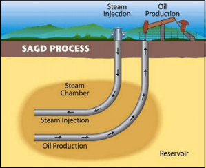
The SAGD, an enhanced oil recovery technology for producing heavy crude oil and bitumen, was initially proposed by Butler and his colleagues [3]. This process is schematically shown in Figure 1. In the SAGD operation, two horizontal wells are placed close to the bottom of a formation, with one several meters above the other. High pressure steam is injected continuously into the upper well, and rises in the formation, forming a steam chamber. The reservoir oil in the steam chamber is heated and becomes mobile due to reduced viscosity. The heated oil flows by gravity into the lower production well. The steam injection and oil production take place continuously and simultaneously. The resulting oil and condensed steam emulsion are then pumped from the producing well to the plant, where bitumen and water are separated. The water is treated and recycled for generating new steam.
As a continuous process, the SAGD technique allows for much higher production rates and thermal efficiency than other in-situ processes and thermal methods and has improved bitumen recovery from the oil sands; at the same time, it has brought great operation challenges including water treatment as it is recycled for steam generation.
Why it is important to remove dissolved silica from SAGD produced water?
The produced water pumped to the surface along with bitumen will be separated (deoiled) and treated. The intensive use of water in the SAGD process makes it essential to reuse and recycle the recovered produced water for steam generation to protect the environment and to minimize costs. The SAGD produced water is characterized by its high silica content (150−400 ppm as SiO2), calcium (5−150 ppm), and magnesium hardness (5−75 ppm), as well as other impurities. Silica-related species can be classified as dissolved, colloidal, or particulate depending on their size. Under the typical conditions of SAGD produced water, silica mostly exists as dissolved silicate. Silica and other impurities in SAGD produced water must be removed to achieve quality requirements for recycle. These contaminants can pose great challenges to the process. Specifically, silica can form silicate scales in the steam generators; silica fouling can damage boiler drum, plug tubes, cause equipment failure. Efficient removal of silica from produced water will increase thermal efficiency in steam generation and reduce the risks caused by these damages.
Silica removal by surface complexation
Among technical approaches for SAGD water treatment, magnesium oxide (MgO) has been used in the lime softening operation to remove silica from produced water [4]. The mechanism and chemical reactions leading to silica removal by MgO include: (1) magnesium hydroxide (brucite) precipitates during the MgO slaking step with a fraction of Mg(OH)2 being located at the solid-liquid interface; (2) The chemically reactive surface Mg(OH)2 groups (denoted as ≡Mg(OH)20) bind with dissolved silica; (3) the bonded silica becomes part of the brucite solid and is removed in the clarifier. Although a realistic process of silica fixation by MgO may have been a combination of surface adsorption and precipitation of the dissolved silica as magnesium silicate minerals, the surface complexation mechanism has been shown to match the measured silica concentrations in some silica removal case studies by appropriately selecting fractions of reactive brucite surface sites, because the fraction of reactive surface Mg(OH)2 can depend on the slaking process, the properties of the calcined MgO, and the source of MgO. Surface complexation has been proven to be a reasonable silica fixation mechanism.
The overall reactions for the silica removal through MgO surface complexation can be represented by the following steps:
Reactions in the aqueous phase:
2H2O ↔ H3O+ + OH– (ionization of water)
SiO2 + OH– ↔ HSiO3– and HSiO3– + OH– ↔ SiO3-2 + H2O (ionization of silica)
MgO slaking reaction:
MgO + H2O → Mg(OH)2 (brucite)
Surface arrangement (where x is the fraction of reactive brucite surface)
Mg(OH)2 (brucite) → (1-x)·Mg(OH)2 (inner crystal) + x· ≡Mg(OH)20 (surface species)
Surface ionization:
≡Mg(OH)20 + H3O+ ↔ ≡Mg(OH)2H+ + H2O
≡Mg(OH)20 + OH– ↔ ≡Mg(OH)O– + H2O
Surface complexation:
≡Mg(OH)2H+ + HSiO3– ↔ ≡MgOH-HSiO30 + H2O
≡Mg(OH)O– + SiO3-2 + H2O ↔ ≡MgOH-SiO3– + 2OH–
In this process, ionization of silica to form silicate anions, ionization of the surface ≡Mg(OH)20, and surface complexation are all pH dependent. These reactions also depend on temperature and other system conditions. Appropriate modelling for representing these reactions can ensure accurate prediction of silica removal efficiency and provide insights into the development of the silica removal technology in SAGD water treatment. This requires accurate models in both solution chemistry and reactions on the solid-liquid interface.
OLI simulation tools for predicting silica removal
OLI has developed advanced technologies based on its proprietary thermodynamic model, the Mixed-Solvent Electrolyte (MSE) model [5]. This model has been integrated with the surface complexation double layer model (DLM) [6] which is implemented in the OLI simulation software. The MSE model provides accurate prediction of silica ionization in aqueous solutions and other properties in silica/silicate systems. The silicate speciation predicted from the MSE model will be provided as input to the surface complexation modelling. OLI has developed DLM model parameters based on the combination of predicted solution speciation from the MSE model with the surface complexation double layer theory. Key parameters in the surface complexation model include surface properties (e.g., surface area and surface site density) and the adsorption constants between the reactive MgO surface site and aqueous species (e.g., H3O+, OH–, and silicate anions). These adsorption constants can be temperature dependent. The model predicts the efficiency of silica removal through binding to Mg(OH)2 at the solid-liquid interface, so that conditions for optimal silica removal can be determined through process simulation. It also allows to combine the effects of precipitation of magnesium silicate minerals and surface complexation with MgO for effective silica removal.
How reliable is OLI’s simulation for predicting silica removal?
The OLI model for silicate solution chemistry and silica removal predictions has been developed based on experimental ionization and other solution properties, together with the available adsorption data which have been carefully analysed and critically evaluated. Solution properties and silica ionization can be accurately predicted. Shown in Fig. 2 are the comparison of the experimental and predicted equilibrium constants, pK (= -log K), for the ionization reactions:
SiO2(aq) + 2H2O = HSiO3– + H3O+
HSiO3– + 2H2O = H2SiO4-2 + H3O+
Accurately predicted silica ionization behavior as shown in Fig 1 provides a sound basis for appropriate speciation used in surface complexation modelling to predict silica-MgO surface complexation and its variation with solution pH, concentration, and temperature.
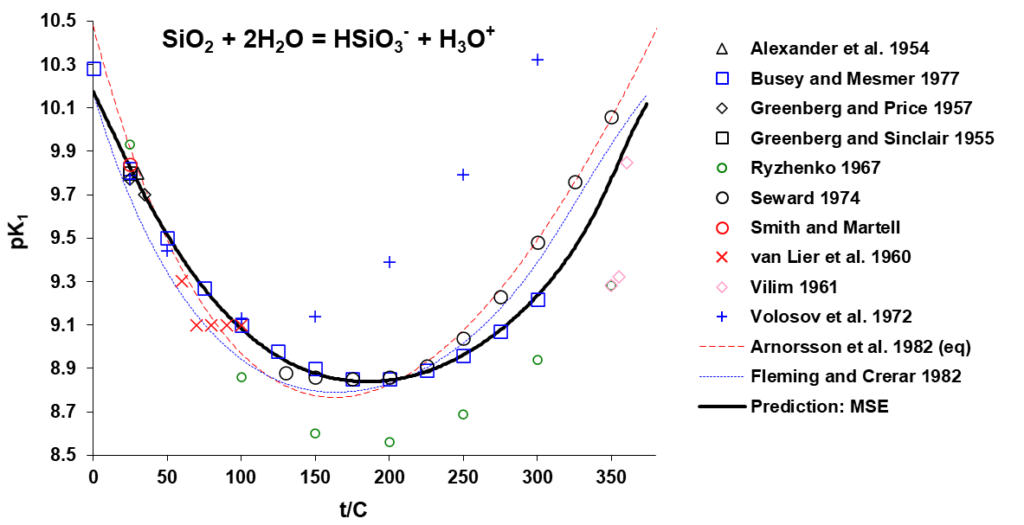
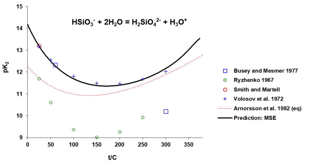
Figure 2. Equilibrium constants for the indicated silica ionization reactions as a function of temperature.
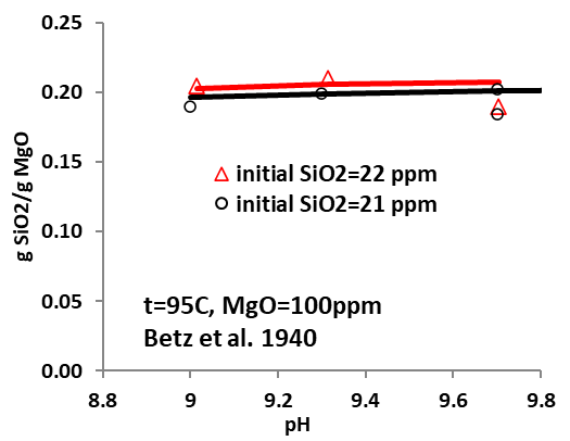
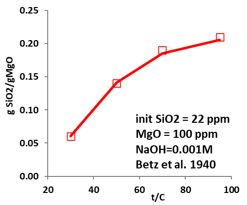
Figures 3-5 demonstrate the amount of silica bound to MgO for their removal by surface complexation. The predicted removal (expressed in gSiO2/gMgO) agrees well with experimental data, demonstrating that the model can provide an efficient and reliable tool to accurately predict silica fixation through surface adsorption under varying conditions. It is noteworthy, however, that the surface properties of MgO used in silica removal may be affected by their sources and obtainment, which will impact the surface fractions that can bind with silica, thus affecting the removal efficiency. Detailed analysis may be required when the model is applied so that reasonable and reliable predictions can be obtained.
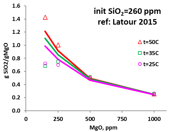

Figure 3. Amount of SiO2 removed by MgO (in gSiO2/gMgO) as a function of added MgO (in ppm) and temperature.
What tools are available for predicting effective silica removal?
The OLI System’s thermodynamic property package, which implements the MSE model and the surface complexation double layer model with the capability of predicting silica removal through surface adsorption is available in OLI Studio and OLI Flowsheet ESP.
Contact OLI for more information or to schedule a meeting with an OLI expert.
References
- Independent Statistics & Analysis, U.S. Energy Information Administration, www.eia.gov
- “Energy Outlook 2035 booklet”, bp.com/energyoutlook
- Butler, R. M. and Stephens, D. J.: 1981, Journal of Canadian Petroleum Technology 20(2), 90–96
- Zhang, et al. Ind. Eng. Chem. Res. 2021, 60, 1839−1849
- Wang P., Anderko A., Young R. D., Fluid Phase Equilibria 203 (2002) 141-176
- Dzombak, D. A.; Morel, F. M. M. Surface Complexation Modeling: Hydrous Ferric Oxide; John Wiley & Sons: New York, 1990.