


Industrial membrane plants often require hundreds to thousands square meters of membrane area to perform a separation required on a useful scale. Therefore, methods of economically and efficiently packaging large areas of membrane (e.g., membrane modules) are required. The choice of the most suitable membrane module type for a particular membrane separation must balance a number of factors including but not limited to manufacturing cost, concentration polarization, fouling control, permeate-side pressure drop and suitability for high pressure operation. For reverse osmosis (RO) membrane in seawater/industrial/brackish water application, spiral-wound modules are most commonly used, however, plate-and-frame and tubular modules are limited to a few applications in which membrane fouling is particularly severe. There are only limited applications of hollow fiber reverse osmosis modules.
A RO membrane system includes a set of RO membrane elements connected sequentially in series format and housed in a pressure vessel. The arrangement of the RO system can be single or double pass with the specific geometry of the pressure vessel arrangement described in stages, while the specifics of pressure vessels arrangement inside a stage is called an array. It is important to understand the terms “stage” and “pass” which are often perceived as the same thing. The terms “stage” and “pass” are prevalent in RO membrane industry and often used in describing a process, thus, it is important to understand the difference between a 1 and 2 -stage RO and 1 and 2 -pass RO.
As part of OLI’s commitment to industrial water treatment simulation, OLI has developed a RO membrane block within the software OLI Flowsheet: ESP. The RO block can study a specific chemistry in combination with one or more vendor-supplied membranes to simulate performance of a given membrane. The software is vendor-independent and can be used to screen different membranes for optimal membrane selection, or for optimizing membrane performance within a flowsheet environment.
1-stage RO system is the simplest of all, and inside the module, the concentrate of first element becomes the feed to the second, and so on. In a 1-stage RO system, the feed water enters the RO system as one stream, and the permeate and concentrate exits through the corresponding manifolds (Fig 1a). Two or more vessels are also arranged in parallel to form 1-stage system as required by design or to achieve a permeate quality. Feed, concentrate and permeate lines from the parallel pressure vessels are connected to the corresponding manifolds (Fig 1b).
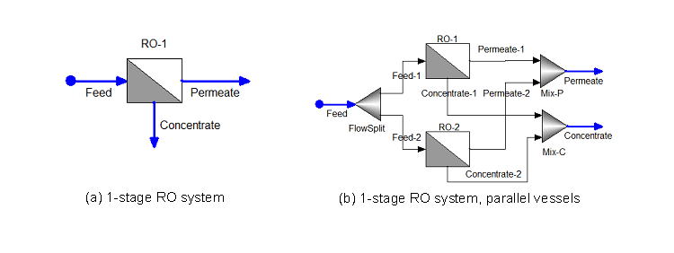
Fig 1: (a) 1-stage RO system, single vessel, and (b) 1-stage RO system, parallel vessels
Multi-stage systems are required for higher system recovery rates. In a 2-stage RO system, the concentrate from the first stage becomes the feed water to the second stage. The permeate water from first stage is collected and combined with the permeate from the second stage (Fig 2). Additional stages increase the recovery of the system. It is to be noted that 2-stage systems are sometimes used to achieve higher recovery without stretching the single element recovery limit (e.g., it is a design consideration whether to stretch element recovery in the module or use additional stages).
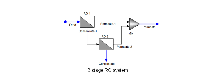
Fig 2: 2-stage RO system
A stand-alone RO system where feed passes through the membrane and produces permeate/concentrate is considered as single “pass” or 1-pass. The difference between a 1-pass RO system and a 2-pass RO system is that for a 2-pass RO, the permeate of the first pass RO is the feed to the second pass RO. A 2-pass RO system is generally needed to produce a much higher quality of permeate because it has essentially passed through two RO systems. The concentrate of the second pass RO is generally recycled back to the feed of the first pass RO because its quality is usually better than the system feed water (Fig. 3). However, without the recycle, this is still a 2-pass RO system.
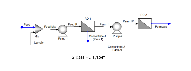
Fig. 3: 2-pass RO system with concentrate of the second pass RO is recycled back to the feed of the first pass RO.
In some applications, a fraction of the system feed water as “blending flow” is taken and added to the permeate (Fig. 4). This blending fraction is carefully chosen to ensure that the required salinity of permeate stream or product water does not exceed. For brackish water application, permeate blending may reduce the number of RO elements required for a specific separation.
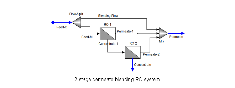
Fig. 4: 2-stage RO system with permeate blending
In some cases, a permeate recirculation to the system feed water may induce constant permeate quality and can prevent instability in operation (Fig. 5).
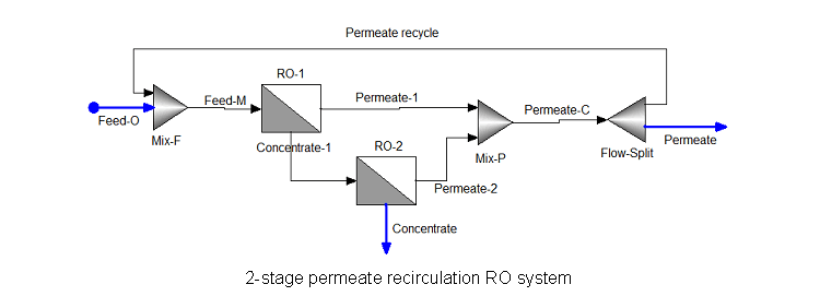
.Fig. 5: 2-stage RO system with permeate recirculation
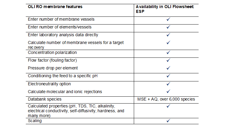
To model the RO membrane, OLI used a solution-diffusion approach to model the transport mechanism inside the membrane. Following this approach, the model calculates the transfer of ions and water through polymeric membranes via a solution diffusion mechanism, because of dissolution of permeates in the membrane materials. For information on a particular membrane, the OLI RO membrane relies on the data from commercial membrane manufacturers who provide product specification data sheet for each type of membrane. In the OLI RO membrane, users can enter number of membrane elements per vessel and total number of vessels in the assembly. Alternatively, users can calculate total number of vessels required (or total membrane area) for a specific recovery. Concentration polarization is approximated using Peclet number and intrinsic enrichments. Flow factor (sometimes referred as fouling factor) is estimated from the water activity reduction unless specified by the users. Users may specify feed side pressure drop per element if available, otherwise it is approximated. There are options for conditioning the feed to a specific pH by choosing a pH acid titrant or base titrant.
Table 1: OLI RO membrane features available within the software OLI Flowsheet: ESP
OLI Systems offers a unique combination of material properties, models and software that uses first-principles based thermodynamic and electrochemical modeling. The OLI property database of over 6,000 species covers over 80 elements of the periodic table. OLI’s physical property methods, and property parameters and data are the ideal choice to suit your simulation needs. OLI Systems has expert scientists, thermodynamicists, engineers and consultants ready to help your thermodynamic data development, defining complex chemistry, conducting sponsored-research and Joint Industry Programs (JIPs) for industrial water treatment solutions.
Contact OLI for more information on our RO and industrial water / wastewater treatment capabilities or to schedule a meeting with an OLI expert. You can find more information on the OLI Flowsheet: ESP software platform here.