


RESOURCES | post
Category: Power Generation


Carbon capture processes
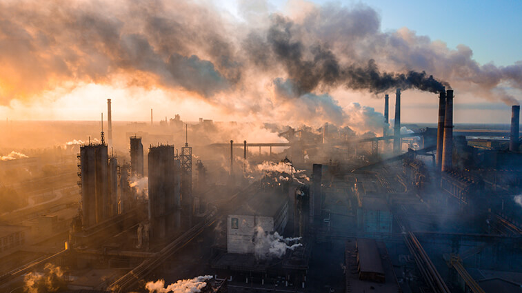
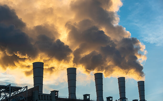
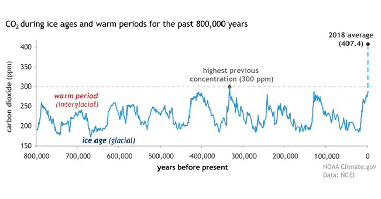
There are many processes being studied to capture carbon dioxide from flue gas after a fossil fuel (e.g., coal, natural gas, or oil) is burned with air to produce electricity. The following graph (1) shows the dramatic increase of carbon dioxide in the atmosphere over roughly the last 100 years compared to the previous 800,000 years. This is mostly due to the burning of fossil fuels for energy.
OLI’s approach to optimize CO2 capture process
For the past several years, @OLI Systems has been collaborating with SRI International to develop their Mixed-Salt Process (MSP) to capture carbon dioxide using ammonia and potassium carbonate (2). Some advantages of this process include lower energy use and low cost industrially available chemicals that do not decompose. The goal is to capture 90% of the carbon dioxide in the flue gas at a 99% carbon dioxide purity, while also keeping ammonia emissions, cooling, and heating as low as possible. OLI Systems has used OLI’s Flowsheet Simulator (OLI Flowsheet: ESP) Platform V10 and the Mixed Solvent Electrolyte (MSE) thermodynamic framework to model and optimize several different flowsheet configurations.
Thermodynamic properties
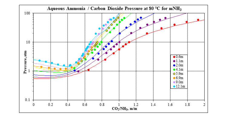
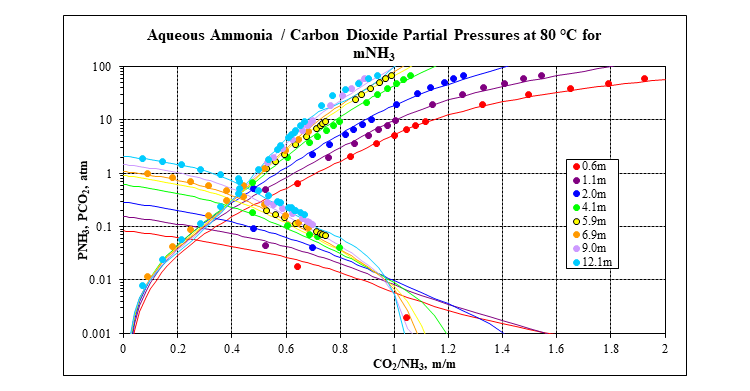
OLI’s MSE framework (3) incorporated in OLI Software Platform V10 is used to calculate all the thermodynamic properties that are needed: speciation, vapor-liquid equilibria, solid-liquid equilibria, enthalpies, heat capacities and densities. It has a complete database for many carbon capture systems, including the mixed-salt system: water – ammonia – carbon dioxide – potassium carbonate. The following two plots show a comparison of MSE predictions to experimental data for the key water – ammonia – carbon dioxide ternary at 80 °C. Many more plots like this at other isotherms and for many other systems are available in the form of validation spreadsheets.
OLI Flowsheet model
The following flowsheet represents a typical configuration of Mixed-Salt Process for carbon dioxide capture that was modeled using OLI’s Flowsheet Simulator Platform V10.
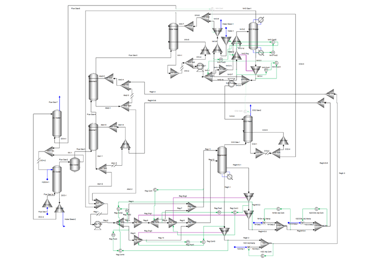
The direct contact cooler is used to cool the flue gas and reduce the moisture content. The flue gas then enters the bottom of two absorbers in series where an ammonia – potassium solvent is used to remove 90% of the carbon dioxide in the flue gas. An ammonia-rich solvent is used in Absorber1 and a potassium-rich solvent is used in Absorber2. Both absorbers cool a portion of their bottom stream and recycle it back to the top to reduce ammonia emissions.
The bottom of both absorbers, rich in carbon dioxide, enter the rich/lean heat exchanger system. This system is modeled using splitters, mixers, energy connections, and controllers. The goal is to maximize the heat recovery, so the regenerator reboiler duty is as low as possible. The heated absorber bottoms streams enter the regenerator where the carbon dioxide is stripped to produce two carbon dioxide-lean streams. These two streams, an ammonia-rich and a potassium-rich are recycled back to the absorbers. Several controllers are included to provide makeup and/or to adjust the flow and ammonia/potassium concentrations of the recycle streams.
The top of Absorber2 goes to the water wash and the top of the regenerator goes to the carbon dioxide wash. The wash columns use water to remove ammonia from these streams. The top of the carbon dioxide wash is the 99% purity carbon dioxide product. The top of the water wash, after going through the direct contact heater, is the cleaned flue gas containing as little ammonia as possible. The bottom of the two wash columns go to the ammonia stripper. The stripper produces the clean water stream that is used in the wash columns. The stripper overhead containing the recovered ammonia and some carbon dioxide is recycled to the regenerator feed. Heat exchange between the ammonia stripper feed and the bottoms is used to reduce the ammonia stripper reboiler duty as much as possible.
Summary
OLI’s Flowsheet Simulator Platform V10 provides an efficient way to optimize carbon capture processes. This includes the ability to easily investigate the effect of many variables: 1) different flue gas rates and compositions, 2) different solvents such as amines, 3) configuration modifications, 4) flow rate and concentrations of the solvent recycle streams between the absorbers and regenerator, and 5) other flow rates as well as pressures and temperatures.
What tools are available to design/simulate carbon capture processes?
The @OLI System’s thermodynamic property package which is based on the MSE model, is available in OLI Studio V10 and OLI Flowsheet ESP V10.
Contact OLI at https:/www.olisystems.com/contact for more information or to schedule a meeting with an OLI expert.
References
- Lindsey R., “Climate Change: Atmospheric Carbon Dioxide”, NOAA Climate.gov, 2020.
- Jayaweera I., Jayaweera P., Kundu P., Anderko A., Thomsen K., Valenti G., Bonalumi D., Lillia S., “Results from Process Modeling of the Mixed – Salt Technology for CO2 Capture from Post – Combustion – Related Applications”, Energy Procedia, 114, 771-780, 2017.
- Wang P., Anderko A., Young R. D., “A Speciation – Based Model for Mixed – Solvent Electrolyte Systems”, Fluid Phase Equilibria, 203, (1-2), 141-176, 2002.


